간단한 CMSIS-DAP 디버거를 만들고 싶다면 꼭 읽어보자.
전체적인 설명페이지는 여기 : http://mbed.org/handbook/cmsis-dap-interface-firmware
CMSIS-DAP interface F/W
한국말로 설명하는 페이지가 만들어 지려나~
일단, 원본 페이지는 http://mbed.org/handbook/cmsis-dap-interface-firmware
결론적으로 보니, CMSIS-DAP Interface를 담당하는 보드는 LPC11U35 시리즈가 부착된 보드를 사용해야 하고 타켓보드로는 Target Flash algorithm이 이미 구현되어 있는 LPC812, LPC1768, KL25Z, KL46Z, KL05Z 중에 하나를 탑재한 보드로 골라야 이 페이지가 제공하고 있는 정보를 실제로 구현해서 검증해 볼 수 있겠다.
소스 저장소
제공하는 기능
- USB Mass Storage Device for drag and drop programming of the target chip
- USB Communications Device Class for Serial Communication with the target chip
- USB HID CMSIS-DAP for debugging
- USB bootloader for updating the interface firmware itself
하드웨어 구조

여기서 중요한 것은 빨간박스 왼쪽이라는 것. PC쪽에도 붙고, Target MCU쪽으로도 붙는 기능을 담당.
그림으로 좀 더 크게 보면, 
PC에 연결
아래 정의된 형태로 기기가 잡힌다.
- MSD, mass storage device class ; 이건 USB Driver로 잡히는 부분
- CDC, communications device class ; 이건 Virtual Serial Port 등으로 쓰이는 것..
- HID, human interface device class ; 이건 ... 조사를 좀더
Target MCU에 연결
여러가지 핀들이 연결되지만, 기본적으로
- SWD + Reset
- UART
- Sleep and Wake (Not currently implemented, reserved for future use)
소프트웨어 부분
아래의 내용들을 참고하면 되겠다.
공유 코드들
Bootloader든 CMSIS-DAP Interface F/W 든 공통적으로 사용되는 코드/미들웨어부분은 아래 폴더에 저장되어 있음
- shared\cmsis: The CMSIS-CORE software layer
- shared\rtos: The RTX operating system
- shared\USBStack: The USB Device middleware
Bootloader
현재 LPC11U35 지원코드만 공개되어 있음, 위치는 여기로
bootloader\mdk\lpc11u35\lpc11u35_bootloader.uvproj
At startup it checks the state of a given pin, default high by pull-up resistor: 기본적으로 풀업이 된 핀이라는 것.
- If the pin is high: it simply relocates the vector table to point to the interrupt handlers of the CMSIS-DAP Interface Firmware and then it jumps to its start address.; USB 디바이스를 잡고, bin 코드 카피을 기다리는 모드로 진입
- If the pin is low: it enumerates as a mass storage device, waiting for a new firmware image to be flashed using In Application Programming (IAP) ; 인터페이스 펌웨어 자체를 변경하고자 하면 이런 모드로 진입해야 함..
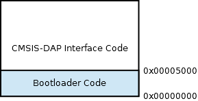
프로그램의 구성은 아래 그림과 같이 나누어져 있다.

새로운칩에는??
나중에 시도할 때 좀 더 자세히 보기로 하고 여기서 스킵~~ 일단, 처음에는 LPC11U35를 쓰는 것이 단순한 방법~
The current implementations are:
- LPC11U35:
bootloader\hal\TARGET_NXP\TARGET_LPC11U35
Flash 알고리즘
Target MCU에 새로운 이미지 파일(F/W bin 파일)을 프로그램할 수 있도록 하는 flash algorithm을 Target MCU의 RAM영역에 로드되어야 한다.
이 알고리즘들은 각각 개발해야 하는데,
position independent code로 컴파일 된 프로그램 결과물을 binary blob라 불리는 배열코드로 변경한다음, 인터페이스 코드에 복사하여 넣은 다음 코드를 개발하면 된다. 아래의 Pythone 코드 사용법을 보고 문장을 고침 문맥이 이상하다. 수정이 필요함
일단 제공되는 2가지 MDK 프로젝트는 다음과 같다. We provide two such MDK projects for generating the flash algorithms for two family of microcontrollers:
interface\flash_algo_mdk\LPC_IAP\LPC_IAP.uvproj: flash algorithm for NXP LPC familyinterface\flash_algo_mdk\MKXXX\MKXX.uvproj: flash algorithm for Freescale MK family
당연한 얘기지만, 위의 프로젝트들은 multiple configurations을 가지고 있다. 각각 다른 Flash size 별로
일단, 만들어진 코드들은 제공되는 Python script 로 c code 형태로 변경하여 원하는 Target에 맞는 인터페이스 F/W 프로젝트에 포함시킬 수 있다. 스크립트의 사용은 아래와 같다.
- 일단 output elf binary ".axf"파일을
tools\tmp\flash_algo.axf에 복사한다. - 다음 코드를 수행한다.
1 | tools> python flash_algo_gen.py |
- 그럼 tools\tmp\flash_algo.txt 파일이 생성된다. 아래와 같은 파일이다.
1 2 3 4 5 6 7 8 9 10 11 12 13 14 15 16 17 18 19 20 21 22 23 | const uint32_t flash_algo_blob[] = { 0xE00ABE00, 0x062D780D, 0x24084068, 0xD3000040, 0x1E644058, 0x1C49D1FA, 0x2A001E52, 0x4770D1F2, /*0x020*/ 0x28100b00, 0x210ed302, 0xd0eb01, 0x494f4770, 0x607af44f, 0x60084449, 0x2100484d, 0x21aa7001, /*0x040*/ 0x21557301, 0x21017301, 0x1c40f800, 0x47702000, 0x47702000, 0x41f0e92d, 0x20324c46, 0x2500444c, /*0x060*/ 0xe884261dL, 0xf1040061L, 0x4f430114, 0x46204688, 0x696047b8, 0x2034b960, 0x61e884, 0x4641483b, /*0x080*/ 0x68004448, 0x462060e0, 0x696047b8, 0xd0002800L, 0xe8bd2001L, 0xe92d81f0L, 0xf7ff41f0L, 0x4d35ffc1, /*0x0A0*/ 0x444d4604, 0xe9c52032L, 0xf1050400L, 0x4e320114, 0x4628460f, 0x47b060ac, 0xb9686968L, 0xe9c52034L, /*0x0C0*/ 0x482a0400, 0x444860ac, 0x68004639, 0x462860e8, 0x696847b0, 0xd0dc2800L, 0xe7da2001L, 0x41f0e92d, /*0x0E0*/ 0x64614, 0x4825d11d, 0x12fcf8d4, 0xd03a4281L, 0x42814823, 0x4823d037, 0xd0344281L, 0x4030ea4f, /*0x100*/ 0xd0304281L, 0x100e9d4, 0xe9d44408L, 0x44111202, 0x69214408, 0x69614408, 0x69a14408, 0x42404408, /*0x120*/ 0x463061e0, 0xff7cf7ffL, 0x21324d12, 0x4f12444d, 0x1000e9c5, 0x114f105, 0x468860a8, 0x47b84628, /*0x140*/ 0xb9806968L, 0xe9c52033L, 0xf44f0600L, 0xe9c57000L, 0x48064002, 0x44484641, 0x61286800, 0x47b84628, /*0x160*/ 0x28006968, 0x2001d095, 0xe793, 0x4, 0x400fc080, 0x8, 0x1fff1ff1, 0x4e697370, /*0x180*/ 0x12345678, 0x87654321L, 0x0, 0x0, }; static const TARGET_FLASH flash = { 0x1000002F, // Init 0x10000051, // UnInit 0x10000055, // EraseChip 0x10000097, // EraseSector 0x100000DD, // ProgramPage |
Interface
현재, 2가지 모델이 지원된다. 공개된 것이 2개라는, 각 벤더별로 각 회사에서 지원하고 있겠지..
- LPC11U35: interface\mdk\lpc11u35\lpc11u35_interface.uvproj
- KL25Z: interface\mdk\kl25z\kl25z_interface.uvproj
각 프로젝트는 여러 설정을 지원한다.
- Support different targets: providing a different flash algorithm and reset/unlock sequences
- Standalone build at address 0x0 (useful during development for better debugging) / Bootloader build at address 0x5000 ready to be loaded by the bootloader.
새로운 Target MCU에 대한 지원
아래 2 파일들을 잘 구성하면 된다.
- target_flash.h: Implements an API to load a new binary into the flash of the target, largely generated from the above Flash Algorithm project
- target_reset.c: provides function in order to unlock/set the target in a specific state
현재 이미 구현된 target은 다음과 같다 :
- LPC812: interface\target\hal\DBG_NXP\DBG_LPC812
- LPC1768: interface\target\hal\DBG_NXP\DBG_LPC1768
- KL25Z: interface\target\hal\DBG_Freescale\DBG_KL25Z
- KL46Z: interface\target\hal\DBG_Freescale\DBG_KL46Z
- KL05Z: interface\target\hal\DBG_Freescale\DBG_KL05Z
새로운 Interface Chip에 포팅
잘 만든 USB IP가 들어간 새로운 칩이 있다면 이 Interface F/W을 포팅할 수 있다.일단 이 이슈는 스텝전이고, LPC11U35에 해 본 다음 진행할 것이라 나중에 보강해 보자.
Concatenated Production Image
양산시 이미지 합치기 이렇게 번역이 되건만, 내용파악이 정확히 되지 않아.나중에..

